
Cách lựa chọn dao tiện
Thứ Năm,
27/02/2025
Lê Anh Tuấn
How to choose correct turning insert
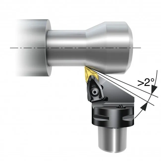
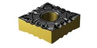
There are many parameters to consider when choosing turning insert. Carefully select insert geometry, insert grade, insert shape (nose angle), insert size, nose radius and entering (lead) angle, to achieve good chip control and machining performance.
- Select insert geometry based on selected operation, for example finishing
- Select the largest possible nose angle on the insert for strength and economy
- Select the insert size depending on the depth of cut
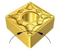
- Select the largest possible nose radius for insert strength
- Select a smaller nose radius if there is a tendency for vibration
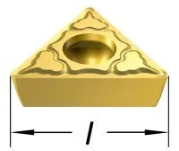
l = cutting edge length (insert size)
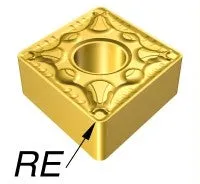
RE = nose radius
Nose angle
Turning insert geometry
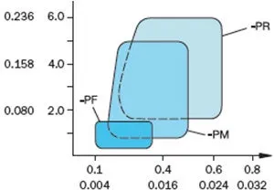
Turning geometries can be divided into three basic styles that are optimized for finishing, medium and roughing operations. The diagram shows the working area for each geometry, based on acceptable chip breaking, in relation to feed and depth of cut.
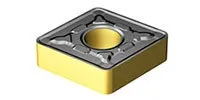
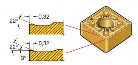
Roughing
High depth of cut and feed rate combinations. Operations requiring the highest edge security.
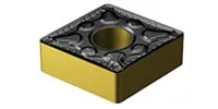
Medium
Medium operations to light roughing. Wide range of depth of cut and feed rate combinations.
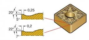
Finishing
Operations at light depths of cut and low feed rates. Operations requiring low cutting forces.
|
ap |
|||
| inch | mm | ||
 |
Feed fn | ||
| mm | |||
| inch |
Above example illustrates the offer for steel, there are other options available for all material groups.
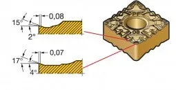
Turning Wiper geometry
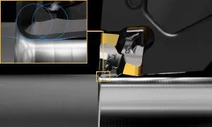
Use wiper inserts for improved surface finish with standard cutting data, or, maintained surface finish at substantially higher feed rate.
The -WMX wiper geometry is first choice, and is a good starting point for most applications. When conditions change, there is always a productive alternative.
Choose a positive wiper geometry to lower forces and maintain productivity in case of vibration problems.
Choose wiper geometry as follows:
-WL: For improved chip control when moving to a lower fn/ap.
-WF: Improves chip control at a lower fn/ap. Also for lower cutting forces when vibrations occur.
-WMX: Always first choice within the wide chip application area. Provides maximum productivity, versatility and the best results.
-WR: When a stronger edge line is needed, for example, for interrupted cuts.
Bài viết khác

Tiện các loại vật liệu khác nhau
27/02/2025

Sử dụng nước làm mát trong gia công tiện
27/02/2025

Cách lựa chọn dao tiện
27/02/2025

Tăng tuổi thọ dao tiện
27/02/2025

Phương pháp đạt chất lượng sản phẩm tiện
27/02/2025