
Phương pháp đạt chất lượng sản phẩm tiện
Thứ Năm,
27/02/2025
Lê Anh Tuấn
Turning components: How to achieve good component quality
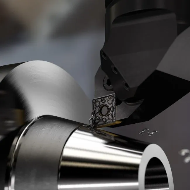
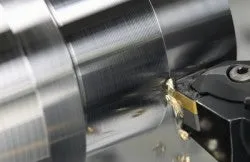
To achieve quality turned components, chip control is one of the most important factors to consider. Choose the correct cutting data and follow our application tips for good component quality.
Successful chip control
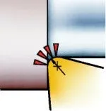
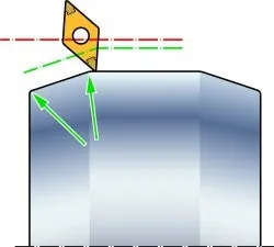
Chip control is one of the key factors in turning and there are three principle chip breaking alternatives:
- Self-breaking (for example grey cast iron)
- Breaking against the tool
- Breaking against the workpiece
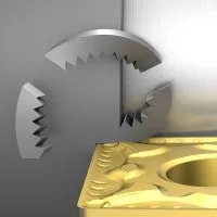
Self-breaking
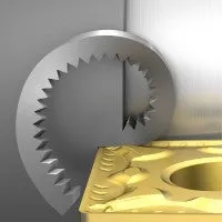
Breaking against the tool
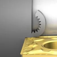
Breaking against the workpiece
Factors that influences chip breaking
- Insert geometry: Based on the width of the chip groove and the micro- and macro geometry design, the chip will be open or more compressed
- Nose radius: Smaller nose radius controls the chip more than a bigger nose radius
- Entering (lead) angle: Depending on angle, the chip is directed in different ways; towards shoulder or out from shoulder
- Cutting depth: Depending on the workpiece material, a larger cutting depth will influence the chip breaking, leading to bigger forces to break and remove the chip
- Feed: A higher feed will in general create stronger chips. Can in some cases help chip breaking and chip control
- Cutting speed: Change of cutting speed can influence the chip breaking performance
- Material: A short chipping material (for example cast iron) is in general easy to machine. For materials with excellent mechanical strength and resistance to creep
(the tendency for solids to slowly move or deform under stress, for example, Inconel), the chip breaking is of greater concern
Cutting data for turning
Always consider the machine, tool, insert, and material when choosing the correct speeds and feeds for turning.
- Start at a low feed rate to ensure insert security and surface finish, then increase feed rate to improve chip breaking
- Run at a cutting depth larger than the nose radius. This will minimize the radial deflection of the insert, which is important in internal machining
- Setting the cutting speed too low will result in inadequate tool life. Always run at recommended cutting speed, vc m/min (ft/min)
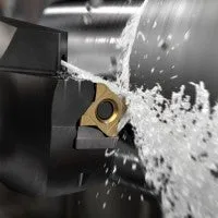
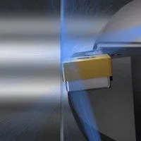
Improve turning component quality with coolant
When coolant is correctly applied, it will increase process security and improve the tool performance and component quality. Consider the following when using coolant:
- Tools with precision coolant are strongly recommended for finishing applications
- The required coolant pressure to break the chip depends on the nozzle diameter (outlet), material being machined, the depth of cut, and feed
- The coolant flow required depends on the pressure and the total coolant delivery area of the coolant holes
- In medium and roughing applications it is recommended to use under coolant
- For finishing operations it is recommended to use both precision coolant as well as under coolant
Solve challenges with correctly applied coolant
- Chip control issues: Use over coolant
- Dimensional issues: Normally caused by too high temperature – use both over- and under coolant and as much pressure as possible
- Poor surface quality: Use over coolant if the defect is caused by chips
- Unpredictable tool life in roughing operations: Use under coolant only
- Unpredictable tool life in finishing operations: Use both over- and under coolant
- Poor chip evacuation in internal operations: Use both over- and under coolant, and as high pressure as possible
How to apply coolant and cutting fluid in turning
How to achieve good surface finish for turning components
General rules for surface finish:
- The surface finish can often be improved by using a higher cutting speed
- The insert geometry (neutral, positive and negative rake angles, as well as positive clearance angles) influences the surface finish
- The selection of insert grade has some influence on surface finish
- In the event of vibration tendencies, select a smaller nose radius
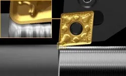
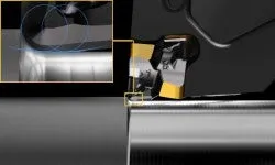
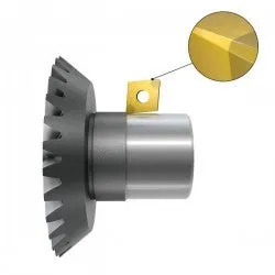
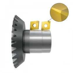
Wiper insert
Wiper inserts are capable of turning components at high feed rates - without losing the capability for generating good surface finishes or chip-breaking ability.
A general guideline is: Two times the feed-rate, same surface finish. Same feed-rate, twice as good surface finish.
Wiper inserts are designed to smooth the surface generated as the insert is fed along the workpiece, the wiper effect is primarily designed for straight-line turning and facing.
Standard radius
Wiper radius
Comparison, standard insert versus wiper insert based on feed rate
Note! All values for standard radius are theoretically calculated. The values for wiper radius are based on experimental values in low alloyed steel.
| Feed mm (inch) |
Standard RE 0.4 mm (0.016 inch) Ra µm (µinch) |
Wiper (-WF/-WM) RE 0.4mm (0.016 inch) Ra µm (µinch) |
Standard RE 0.8 mm (0.031 inch) Ra µm (µinch) |
Wiper (-WMX) RE 0.8 mm (0.031 inch) Ra µm (µinch) |
| 0.07 (0.003) | 0.31 (12.4) | 0.30 (12.0) | - | - |
| 0.10 (0.004) | 0.63 (25.2) | 0.32 (12.8) | 0.31 (12.4) | - |
| 0.12 (0.005) | 0.90 (36.0) | 0.45 (18.0) | 0.45 (18.0) | - |
| 0.15 (0.006) | 1.41 (56.4) | 0.70 (28.0) | 0.70 (28.0) | 0.25 (10.0) |
| 0.18 (0.007) | 2.03 (80.8) | 1.00 (40.0) | 1.00 (40.4) | 0.30 (12.0) |
| 0.20 (0.008) | 2.50 (100.0) | 1.25 (50.0) | 1.25 (50.0) | 0.35 (14.0) |
| 0.22 (0.009) | 3.48 (139.2) | 1.74 (69.6) | 1.74 (69.6) | 0.40 (16.0) |
| 0.25 (0.010) | - | - | 2.25 (90.0) | 0.45 (18.0) |
| 0.28 (0.011) | - | - | 2.82 (112.8) | 0.50 (20.0) |
| 0.30 (0.012) | - | - | 3.23 (129.2) | 0.55 (22.0) |
| 0.35 (0.014) | - | - | 4.40 (176.0) | 0.60 (24.0) |
| 0.40 (0.016) | - | - | 5.75 (230.0) | 0.70 (28.0) |
| 0.45 (0.018) | - | - | 8.54 (341.6) | 1.1 (44.0) |
| 0.50 (0.020) | - | - | 10.55 (422.0) | 1.3 (51.0) |
| Feed mm (inch) |
Standard RE 1.2 mm (0.047 inch) Ra µm (µinch) |
Wiper (-WMX) RE 1.2mm (0.047 inch) Ra µm (µinch) |
Standard RE 1.6 mm (0.063 inch) Ra µm (µinch) |
Wiper (-WMX) RE 1.6 mm 1) (0.063 inch) Ra µm (µinch) |
| 0.15 (0.006) | 0.47 (18.8) | - | - | - |
| 0.18 (0.007) | 0.68 (27.2) | - | - | - |
| 0.20 (0.008) | 0.83 (33.3) | 0.3 (12.0) | 0.63 (25.2) | - |
| 0.22 (0.009) | 1.16 (46.4) | 0.3 (12.0) | 0.87 (34.8) | - |
| 0.25 (0.010) | 1.50 (60.0) | 0.4 (16.0) | 1.12 (44.8) | 0.3 (12.0) |
| 0.28 (0.011) | 1.88 (75.2) | 0.4 (16.0) | 1.41 (56.4) | 0.35 (14.0) |
| 0.30 (0.012) | 2.16 (86.4) | 0.4 (16.0) | 1.62 (64.8) | 0.4 (16.0) |
| 0.35 (0.014) | 2.93 (117.2) | 0.5 (20.0) | 2.20 (88.0) | 0.4 (16.0) |
| 0.40 (0.016) | 3.83 (153.2) | 0.65 (26.0) | 2.88 (115.2) | 0.4 (16.0) |
| 0.45 (0.018) | 5.70 (228.0) | 0.85 (34.0) | 4.27 (170.8) | 0.5 (20.0) |
| 0.50 (0.020) | 7.03 (281.2) | 1.15 (46.0) | 5.27 (210.8) | 0.7 (28.0) |
| 0.55 (0.022) | 8.51 (340.4) | 1.2 (48.0) | 6.38 (255.2) | 0.9 (36.0) |
| 0.60 (0.024) | 10.13 (405.2) | 1.3 (52.0) | 7.59 (303.6) | 1.05 (42.0) |
| 0.65 (0.026) | - | - | 8.91 (356.4) | 1.25 (50.0) |
| 0.70 (0.028) | - | - | 10.31 (413.6) | 1.3 (52.0) |
| 0.85 (0.033) | - | - | 15.24 (609.6) | 1.9 (76.0) |
| 0.90 (0.035) | - | - | 17.09 (683.0) | 2.1 (84.0) |
- Values for 1.6 mm (0.06 inch) radius are based on DNMX insert
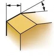
Application tips for external turning
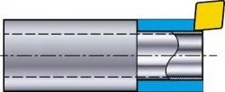
Vibration prone components
Cut in one pass (for example a tube)
It is recommended to machine the whole cut in one pass to direct the force into the chuck/spindle in axial direction.
Example:
Outer diameter (OD) of 25 mm (0.984 inch)
Inner diameter (ID) of 15 mm (0.590 inch)
Depth of cut, ap = 4.3 mm (0.169 inch)
Resulting thickness of the wall = 0.7 mm (0.028 inch)
| OD = 25 mm (0.984 inch) |
ap 4.3 mm (0.169 inch) |
 |
ID = 15 mm (0.590 inch) |
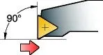
An entering angle close to 90° (lead angle 0°) can be used for directing the cutting forces in axial direction. This leads to minimal bending forces on the component.
Cut in two passes
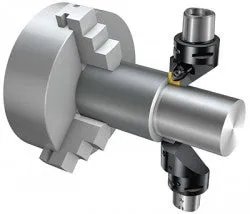
Synchronized upper and lower turret machining will level out radial cutting forces and avoid vibration and bending of the component.
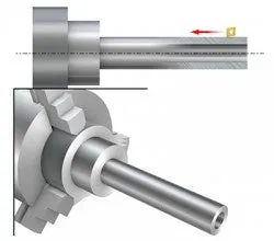
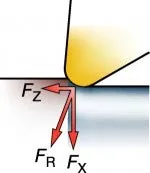
Slender/thin wall components
When turning slender/thin wall components, consider the following:
- Use an entering angle close to 90° (lead angle 0°). Even a small change (from a 91/-1 to a 95/-5 degree angle) will impact the cutting force direction during machining
- The depth of cut,ap, should be larger than the nose radius, RE. A large ap increases the axial force, Fz, and decreases the radial cutting force, Fx, which causes vibration
- Use an insert with sharp edge and small nose radius, RE, that will generate low cutting forces
- Consider using Cermet or PVD grade, to provide wear resistance and a sharp insert edge which is preferable in this type of operation
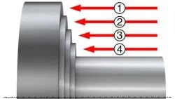
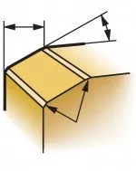
Shouldering/turning shoulder
Follow step 1-5 to avoid damage of the insert edge. This method is very favourable for CVD coated inserts, and may reduce fractures considerably.
Step 1-4:
Keep the distance of each step (1-4) to the same as the feed rate to avoid chip jamming.
Step 5:
Machine the final cut in one vertical cut, starting from outer diameter towards the inner diameter.
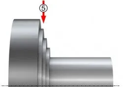
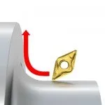
Problems with wrap around chips on the radii can also occur if machining from inner to outer diameter when facing up on the shoulder. Changing the tool path can reverse the chip direction and solve the problem.
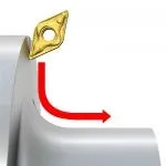
Facing
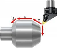
Start with the facing (1) and the chamfer (2). If possible and if geometrical conditions on the workpiece allow it, machine the chamfer (3). The longitudinal cut (4) is the last operation and the insert will have a smooth entering and exit during the machining.
Facing shall be the first operation to set the reference point on the component for the next pass.
Burr formation is often a problem at the end of the cut (when leaving the workpiece). Leaving a chamfer or a radius (rolling over a corner) could minimize or avoid burr formation.
A chamfer on the component will lead to a smoother entry of the insert edge (both in facing and longitudinal turning).
Interrupted cuts
When machining interrupted cuts:
- Use a PVD grade to provide edge line toughness in applications with fast interruptions, for example, hexagonal bars
- Use a tough CVD grade to provide bulk toughness in applications with big components and heavy interruptions
- Consider to use a strong chip breaker to add sufficient chipping resistance
- It can be beneficial to turn off coolant to avoid thermal cracks
Finishing component with undercut (grinding relief)
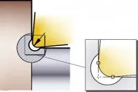
Use the biggest possible nose radius, RE, for longitudinal and face turning, leading to:
- A strong edge and more reliability
- Good surface quality
- Possibility to use high feed
Do not exceed the width of the undercut and perform the undercut as the last operation to remove burrs.
Application tips for internal turning
- Choose the largest possible bar diameter, but at the same time ensure that there is enough room for chip evacuation between the bar and the hole
- Ensure that chip evacuation is sufficient in relation to the cutting data being applied, and the correct type of chips are produced
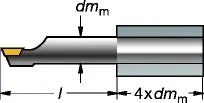
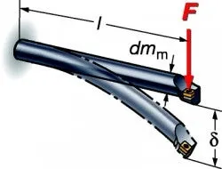
- Choose the smallest possible overhang but, at the same time, ensure that the length of the boring bar allows the recommended clamping lengths. The clamping length should never be smaller than three times the bar diameter
- Use damped boring bars if vibration sensitive parts are produced
- Select an entering angle as close as possible to 90° (0° lead angle) to direct the cutting forces along the boring bar. The entering angle should never be smaller than 75° (-15° lead angle)
- As a first preference, the indexable insert should have a positive basic shape and a positive insert geometry to minimize tool deflection
- Select an insert nose radius that is smaller than the cutting depth
- Insufficient cutting edge engagement can increase vibrations caused by friction during cutting. Choose a cutting edge engagement that is bigger than the nose radius for a good cutting action
- Excessive cutting edge engagement (large depth of cut and/or feed) can increase vibrations caused by tool deflection
- Uncoated or inserts with thin coatings normally produce lower cutting forces compared to thick coated inserts. This becomes especially important when the relationship between length/diameter is large. A sharp cutting edge normally improves hole the quality by minimizing vibration tendencies
- A geometry with an open chip breaker can often be more advantageous for internal turning
- An insert grade with a higher level of toughness may be a consideration in some operations, as it can cope with any risks of chip jamming or vibration tendencies
- Consider alternative tool paths if chip formation needs to be improved
Application tips for hard part turning
In addition to the general recommendations for turning, there are some key factors to consider for hard part turning (if production process includes own preparation of component before hardening):
- Avoid burrs
- Maintain close dimensional tolerances,
- Chamfer and produce radii in the soft stage
- Do not enter or leave cuts abruptly
- Enter or leave by rolling into or out of the cut
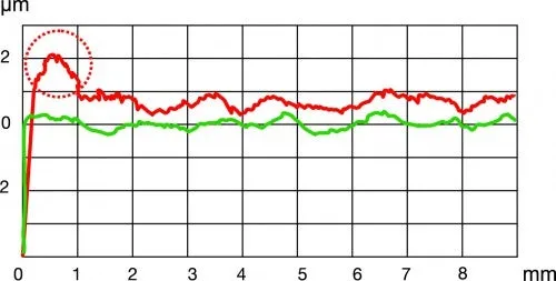
Surface measurements
X-axis: Feature length
Y-axis: Diameter deviation
Critical surface
Set-up
- Good machine stability, clamping and alignment of workpiece are crucial
- As a guideline, a workpiece length-to-diameter ratio of up to 2:1 is normally acceptable for workpieces that are only supported on one end. If there is additional tailstock support, this ratio can be extended
- Note that a thermally symmetrical headstock and tailstock design will add extra dimensional stability
- Use the Coromant Capto® system
- Minimize all overhangs to maximize system rigidity
- Consider carbide shank boring bars and Silent Tools for internal turning
Insert micro geometry
Two typical edge preparations for CBN inserts are S-type and T-type.
- S-type: Has the best edge line strength. Resistant against micro chipping and ensures consistent surface quality.
- T-type: For best surface finishes in continuous cuts, and minimized burr formation in interrupted cuts. Lower cutting forces.
S-type
Chamfer with light honing
T-type
Chamfer with no honing
Insert corner geometry
- If conditions are stable, always use wiper geometry for best surface finish.
- Use insert with low entering angle approach when productivity demands are high.
- A normal radius insert should be used only when stability is poor (slender workpiece etc.).
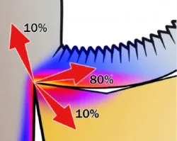
Wet or dry machining
Hard part turning without coolant is the ideal situation, and is entirely feasible. Both CBN and ceramic inserts tolerate high cutting temperatures, which eliminate the costs and difficulties associated with coolants.
Some applications may require coolant, for example, to control the thermal stability of the workpiece. In such cases, ensure a continuous flow of coolant throughout the entire turning operation.
Generally, the heat generated when machining is distributed into the chip (80%), workpiece (10%) and insert (10%). This shows the importance to evacuate the chips from the cutting edge zone.
Cutting data and wear
High heat in the cutting edge zone reduces the cutting forces. Therefore a cutting speed that is too low generates less heat and can cause insert breakage.
Crater wear gradually affects the insert strength, but does not affect the surface finish as much. In contrast, flank wear gradually affects the dimensional tolerance.
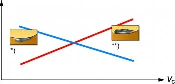
Share of tool life determining wear
*) Flank wear **) Crater wear
Insert change criteria
Predetermined surface finish (B) is a frequent and practical insert change criterion. Surface finish is automatically measured in a separate station and a value is given to a specified finish quality.
For an optimized and a more stable process, set a predetermined number of components (A) as an insert change criteria. This value should be 10–20% less than the predetermined surface finish, the exact figure is determined on a case-to-case basis.
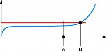
A: Predetermined number of components
B: Predetermined surface finish
X-axis: Number of component
Y-axis: Surface finish
Blue line: Insert wear
Red line: Maximum Ra/Rz value
One-cut strategy
A one-cut "metal removal" strategy is feasible for both external and internal operations. A stable set-up is important and the tool overhang should not exceed the bar diameter in internal turning (1×D). For good machining, we recommend chamfered, lightly-honed inserts and moderate speed and feed.
Advantages
- Quickest possible machining time
- One tool position
Disadvantages
- Difficulties in meeting stringent dimensional tolerances
- Shorter tool life (than two-cut)
- Tolerance deviations due to relatively rapid wear
Two-cut strategy
A two-cut strategy allows unattended machining of high-quality finished surfaces. We recommend roughing inserts with a 1.2 mm (0.047 inch) radius, and the finishing inserts with a chamfer only. Both inserts should have wiper geometry.
Advantages
- Tooling optimized for roughing and finishing
- Higher security, closer tolerances and potentially longer runs between tool changes
Disadvantages
- Two inserts are needed
- Two tool positions
- One extra tool change
Bài viết khác

Tiện các loại vật liệu khác nhau
27/02/2025

Sử dụng nước làm mát trong gia công tiện
27/02/2025

Cách lựa chọn dao tiện
27/02/2025

Tăng tuổi thọ dao tiện
27/02/2025

Phương pháp đạt chất lượng sản phẩm tiện
27/02/2025